Crimp force monitors (CFMs) continue to be a very useful tool in the wire harness industry as well as for many other OEMs requiring crimp quality verification. They can save considerable amounts of time and money in terms of applicator tooling and material scrap, not to mention saving the machine provider from upset customers.
In the last 15 years CFMs have come a long way. They are much more accurate and easier to use than in the past. Some CFM manufacturers focus on user-friendliness, but this tends to make the device less flexible. In contrast, when manufacturers want to give the user a larger degree of control for a greater range of applications, the devices tend to be more complicated to work with. Overall, in spite of improvements, there are still considerable frustrations over using them. Misunderstanding is why we still see machines and presses with CFMs that have been turned off.
CFMs are more commonly implemented on automatic machines than on bench-top because of the rate of termination and the inability for immediate inspection after the crimp. The primary concern is for those who want to implement CFMs on automatic cut, strip, and terminate machines. However, the same principles can be applied to bench-top applications.
To ensure that this article would be thorough and the reader can feel confident that these concepts come from the leaders in the field of crimp force monitoring, I consulted some colleagues in the industry and asked them a few questions: What is the most difficult concept to get across to customers? Where do you see the greatest problems when it comes to CFMs? What are the most critical components to ensure a successful CFM application?
In the answers to Question 1 It was noted that many customers don’t understand that CFMs look at process variation and that there are many variables in the process. You have to consider that different applications may require different CFM parameters. Lastly, interpretation of the CFM data (i.e. curves) can be quite challenging as well.
Most responses to Question 2 pointed to the quality of the materials and applicators, the set-up of the applications and the maintenance of the machines and applicators. However, many problems are caused because of lack of adequate CFM-knowledge.
To ensure a successful CFM application the wire and terminal combination, and subsequently the headroom, have to be correct. The applicators have to be in good condition and the materials have to be good quality. Lastly, for new users, there must be a clear champion for the CFMs. Someone who will take the time to fully understand how to best use them is important.
The complete system has to be considered
Before any CFM system can be used, the process or system has to be stable. When I refer to the system, I am talking about all of the factors that come into play when using CFMs.
When there is a challenging situation involving a CFM, most will only consider the wire, the terminal and the resulting crimp. The crimp might appear to be fine but the CFM has identified it as defective. Many other quality metrics (e.g. crimp height, crimp width, brush length, etc.) only involve one parameter. However, there are many more factors to consider with CFMs. The user must consider the terminals, wire, head room of the application, applicator and press. Each of these variables can affect the resulting crimp curve and all play a part in the resulting forces that the CFM inevitably “sees.” To a lesser degree, even the surrounding area in a plant can affect the consistency of a CFM. Temperature can vary during the day and this can influence press speed and applicator function. Because of these factors the duration and shape of the curve may vary. Unfortunately, the CFM can not isolate specific variable(s) to analyze. In other words, it can not pay attention to some and ignore others and sees them all as a whole. Therefore, the entire system must yield consistent forces in order for the CFM to work properly.
Materials – Terminals & Wire: Not all materials are created equal, and typically, with less cost comes lower quality. Material quality must be consistent.
Terminals: Variations in material stock thickness will cause variation that CFMs might detect. Variations are to be expected to a degree and are usually not the main culprit. But, it is easy to imagine how these variations, if extreme, will adversely affect the ability for the CFM to do its job correctly.
Terminal material may also play a role in how much variation the CFM sees. Gold contacts typically show more variation than the same contact in another material. Gold is a softer metal, and softer materials will exhibit greater variation in forces. This is also the reason why CFMs can not be used on most applications involving pre-insulated terminals. The plastic insulation is too soft and exhibits too much variation.
The way in which the terminals are stored on the spool will affect the way in which the terminals are presented to the applicator. If terminals enter the applicator at odd angles, the crimp forces can be affected. In the example below (Fig 2), the terminals have not been well cared for. The different angle will cause variations in forces. Terminals entering the applicator properly can improve positioning over the anvil and terminal feed.
Wire: Non-concentric wire, as many of us know, will lead to stripping issues. Also, some insulation materials will adhere to the strands and cause stripping problems. If the insulation concentricity or adhesion is not consistent, a problem may be even harder to isolate. However, the CFM can detect variations in the force curve when strands have been nicked or cut easier than we can see the problem with the naked eye. These errors frequently can’t be seen after the crimp has occurred.
The number of strands in a wire also points to the question of whether the CFM can detect one strand out or not. One strand in a 7-strand wire will have a much larger impact on the force of a crimp than one strand of a 41-strand wire. So, if the CFM can see one strand out of a 7-strand wire, 2 or 3 strands may need to be out for a 41-strand wire.
Wire & Terminal Combination: Sometimes customers specify a terminal that is a slightly too large for the wire. It will be more difficult to monitor a 24AWG wire crimped into a terminal that is rated for 24AWG to 20AWG, than it is to monitor the same wire crimped into a similar terminal rated for 24AWG to 28AWG.
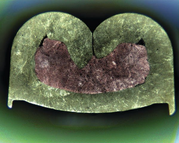
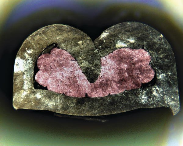
When the wire is small in relation to the terminal, wire placement can be a critical issue. The operator may only see that the terminal is crimped on the end of the wire, but the CFM may be seeing significantly different forces. Below (Fig 3) are cross-sectional pictures of two consecutive crimps in which the wire is undersized for the terminal. The strands of the wire end up in different areas of the crimped terminal, which may result in different forces. This is a case where it might be difficult to use a CFM.
In general, traditional CFMs are most affective for applications of 24AWG and larger. Smaller applications can be difficult. Many of the factors I will discuss in the coming sections play a part, but the primary reason is that the forces related to just crimping the terminal onto the wire are too low compared to the other forces involved. In some cases, it is possible to detect 26AWG applications, but the smaller the application, the more important it is to have a good head room and an applicator that is in good condition.
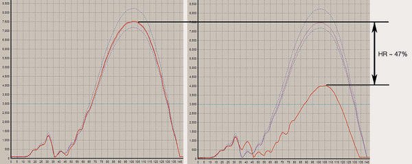
Head Room: The head room of a crimp is the difference in crimping forces when the wire is present and when the wire is not present. This concept plays a large part in answering the question, “Can the CFM detect one strand out?”
Below is an example of a 16AWG wire application. The difference in force with and without the wire is approximately 47%. Therefore, each strand of a 7 strand wire will contribute approximately 6.7% of the force. If it were a 19 strand wire, each strand would contribute roughly 2.5%. This is not exact, but it’s a good approximation. However, if you are using tolerance parameters of ± 4%, you should pick up one strand out on a 7 strand wire but not on a 19 strand wire.
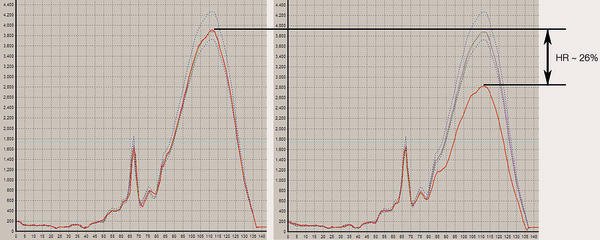
In the example shown in the charts the peak force of the curve drops by only 26% so the affect of the wire on the overall force of the crimp is not nearly as much. In this case, each strand of a 7-strand wire will affect the force by roughly 3.7%; only 1.4% for a 19-strand wire. It is easy to see that if we use the same tolerances of ± 4%, the crimp force monitoring system will probably not see a crimp with one strand out as a defect.
Some applications have a head room of 8% or 10%. These applications will be very difficult to work with, because the majority of the force is just to crimp the terminal.
Applicators: Applicator quality plays a very big role in CFM effectiveness. An applicator that is in bad condition can introduce variation that the CFM will see.
I tested two different applicators with the same wire and terminal on the same automatic machine. The wire was a 16AWG bare copper and the terminal was a rear-feed, brass quick-disconnect; crimp heights and widths were identical. You can see below that the resulting crimps from the two applicators are very similar. However, the older applicator yielded a Cpk value of 0.65 and the newer applicator yielded a Cpk of 1.20. Although both values are not good, there is clearly a difference considering the same wire and terminals were used.
Although the crimp may look fine from the outside, the CFM can see defects because the forces are varying. The biggest contributors to this problem are applicator age and lack of proper maintenance. Over time, applicators will wear out. Noise on the crimp curve can be introduced by any of the following: a ram that does not slide smoothly, worn tooling, inconsistent feed or inconsistent bell-mouth position. These issues might not be perceptible by a quick glance at the resulting crimp, but the CFM will see variation.
The best solution for this is a regular maintenance plan for your applicators. I strongly recommend that anyone considering implementing CFMs should consider the age and quality of their tooling. This is especially true if purchasing a new piece of automatic equipment regardless of the brand. Putting an old, worn-out applicator on a new machine is like putting old tires on a new Corvette. You simply won’t be able to get the optimal performance from the machine.
Presses: In order to use a CFM, the press has to have consistency in speed and shut height as well as be very rigid. The primary concern is with the older presses that many customers use. Many of the older presses are not rigid enough for use with a CFM. However, presses manufactured in the last 5 to 10 years are typically fine, provided they are in good condition.
CFM: a tremendous asset on any production floor
When used properly, CFMs can be a tremendous asset on any production floor. They can save considerable amounts of money in tooling and scrap costs. It is also something that you can sell to your customers because quality monitoring is always seen as a positive.
However, it is important that all factors be considered. For new users, there can be long learning curve. It is important that there is at least one key person involved in the process and that this person is thoroughly trained. This individual must be willing to take the time to really understand the best way to utilize the CFMs.
Users should also understand that there are many components to the system and that the CFM can not analyze certain variables and ignore others. CFMs will look at variation of the entire process, which includes the wire, terminals, applicators, operators and machines. Because of this, not all applications are considered equal. Make sure that your equipment is well maintained and that you are getting consistent quality from your materials. Although there can be challenges, when used correctly, there are many positive benefits of their use. The key to avoiding application problems is detailed knowledge of CFM.
EPPE430
zusammenfassung
Crimp Force Monitoring (CFM) ist eine Herausforderung für die Anwender. Bisweilen werden Anlagen deshalb mit abgeschalteter CFM-Einheit gefahren. Dabei ist CFM kein Hexenwerk und bietet viele Vorteile. Man muss sich mit den vielen Parametern allerdings eingehend auseinandersetzen.
Crimp Force Monitoring (CFM) lance un défi à l’utilisateur. Pour cette raison, certaines installations sont parfois même utilisées avec l’unité CFM désactivée. Pourtant l’utilisation de CFM n’est pas si compliquée et offre de nombreux avantages sur le plan de la qualité et de la rentabilité. Toutefois, il faut se pencher sur les nombreux paramètres.
Share:


