The implementation of selective soldering in the manufacturing process does not merely imply the choice of a system, but involves wider series of considerations that determine the choice of the most suitable technology. Selective soldering has found a wide application with the increasing use of SMT technology where, on product almost completely assembled with surface mounted components and soldered by reflow, the remaining traditional insertion components are few. The selective soldering technological solutions available to avoid manual soldering are somewhat limited: wave soldering with masked carriers, dipping or robotic selective soldering (mini wave, hot iron, laser).
The introduction of selective soldering is basically a choice of process rather than choice of a machine: The choice of the system is a consequence. Every selective soldering procedure is unique and needs its specific management, including dedicated tools. A global view of the product to be soldered is required, as well as a comprehensive understanding of the entire manufacturing process (see table 1).
Process and Materials
As far as the process is concerned, there are several elements that must be considered, such as board, pad and pin size. As everybody knows from day-to-day experience, soldering becomes more difficult as the number of layers increases, when the pad is connected to ground traces, and where there are components with a big thermal mass or, because of their structure, acts as heat sinks. In regard to automated soldering with robotic systems, there are other variables to consider, such as pad geometry and, in particular, the size of annular ring that receives the solder alloy for the solder joint.
In addition there are other critical items which play an important role in the formation of the solder joint such as the size ratio between the annular ring, the hole, the pin size and shape, as well as the length of the lead coming out on the on the solder side of the board. The alloy flows up in the hole by capillarity; consequently if the pin diameter is too small or too large in relation to the hole (at the same time as for a standard size proportion) there are difficulties wicking. If the pin is too long, the heat applied tends to concentrate at the tip, while at the other end the heat tends to dissipate through the body of the component body; in this situation the solder alloy flows towards the hotter zone and ends up on the tip. If it’s too short, there is the opposite problem and the alloy has difficulty to adhere.
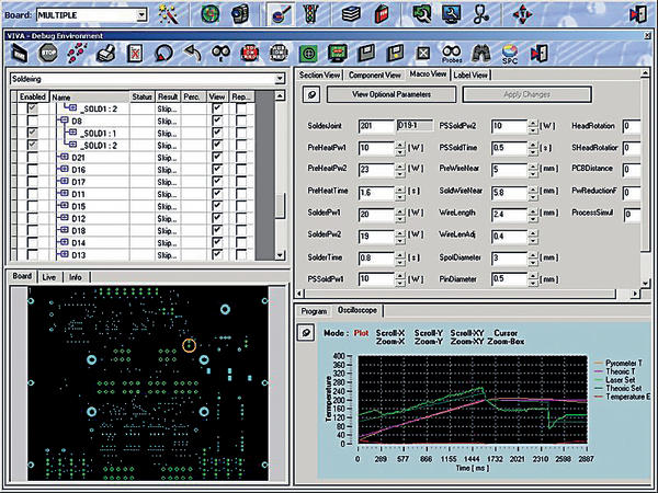
The soldering parameters applied are an integral part of the process, together with the thermal profile and its control. The profile must be set for proper joint formation, based on the characteristics of the board and components, keeping in mind that excessive soldering time have a negative effect on the metallurgic characteristics or may cause possible delamination of the pads. An incorrect profile also causes the formation of voids due to flux entrapment. Working on the principle set down by Lord Kelvin’s statement: “only that which can be measured can be controlled”, the use of a pyrometer is a valid aid in controlling both the soldering process and setting up the correct thermal profile for every single joint during programming.
Since the selective soldering process is an operation that is done after other thermal processes (at least after reflow) it is important to take into consideration possible board distortion, particularly for those that are less than 1,6mm thick; for multi-board panels or for very large boards, even though they may have a high tg degree; this problem can be solved thanks to a planarity sensor, which enables the system to make the necessary adjustments in order to maintain the soldering device aligned with the actual soldering plane. There may be very lightweight through-hole components on the board, therefore both the transport and clamping systems should be designed to avoid any abrupt movements that may jar pins out of place. Of course in any manufacturing process, productivity is an important factor. In the case of selective soldering, productivity must be considered not only in terms of the number of solder joints per unit of time, but also in the speed of a production changeover and minimum maintenance requirements, to ensure maximum throughput and minimum machine downtime.
The substrate material is certainly relevant in determining the degree of success of the production cycle, but even more important to the final result is the surface finishing of pads and component pins. An OSP finish has the lowest performance, followed by NiAu (for its difficulty), while the tin based finishes are proven to be easiest to solder in general, thus less troubling for selective soldering as well. The SnPb alloys (the most used are: 40/60 and 63/37) no longer reserve any surprises, but those commonly known as “lead-free” still present some unknown behavioral aspects, even though the principal characteristics are known, such as less wettability. Alloys with similar compositions, but made by different manufacturers, have very different behaviors under identical process conditions, and diverge completely when the process variables are changed. In fact, every manufacturer pairs the soldering wire with a flux that has its own peculiarities, in different percentages, which is enough to make a difference during the soldering process. The difference becomes evident in the residues, thus board cleanliness at the end of the soldering process.
Soldering system
The selective soldering system most consonant with the manufacturing methods used in western European countries is a robotic type soldering machine. The use of masked carriers and dipping soldering is suited to high volume manufacturing where fixture and mask costs are spread over a high number of boards. Today’s robotic systems use a mini-wave pot with a gripper that carries the board to be soldered, a mobile hot iron (basically a soldering iron) together with a wire feeder unit, or a laser beam pointing to the center of the pad where the solder wire converging on the same point is reflowed using the energy applied by the laser. Induction soldering, on the other hand, is rarely used on electronic boards.
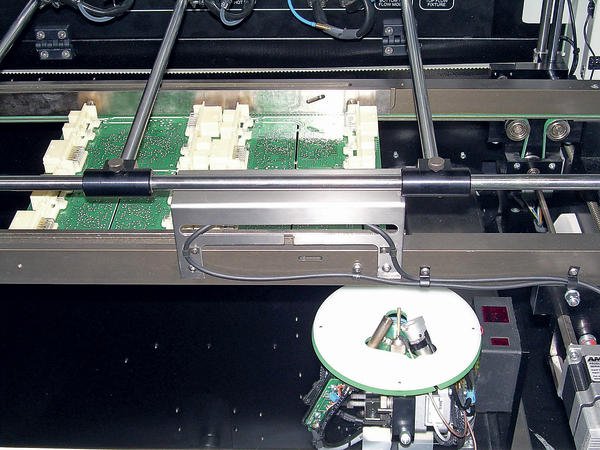
In these types of systems, it is essential that there be a mobile axes system which guarantees a high level of accuracy and repeatability. The soldering head must have the maximum freedom of movement in order to handle almost all possible situations, which is especially important for EMS companies. The nozzle, whether for mini-wave or for wire soldering, must be easy to replace and not be an obstacle when working on high density boards. In the case of wire soldering, the feeder system can be a particularly critical element because of the variability of wire diameters, and its location, which must be as close as possible to the point of solder. The presence of a pyrometer, able to take high speed readings on a small area, facilitates the whole process, due to its double function as an instrument for control and acquisition.
A micro camera can have multiple uses: manual acquisition of the soldering point coordinates, alignment on fiducials in an automated process and recording the images during joint formation, particularly useful when setting up the process.
The software ties all of the subsystems included in the soldering machine together, and must be extremely simple in terms of programming and operation, to make the system user-friendly even for people who are not experts in automation. Among the requested performances, the possibility of importing programming data directly from the board CAD or Gerber files is particularly important. In this case the software can automatically calculate alloy volumes needed to form the joints, determine the suitable laser power level according to the existing thermal mass and calculate the time required not only for melting, but for wettability and wicking as well. A good comprehension of the process and the capabilities of the system at his disposal is an important part of the knowhow that a technician must have. In addition knowledge about the basic elements of soldering and a certain “feel” for the process, makes it easier learn and make best use of the system. The good relationship between the technical production team and the system manufacturer’s sales support engineers is another factor in the equation, and ensures that the user can count on a helpful and skilled presence when needed.
As for most production equipment, it is important to pay attention to the environment where the soldering system is installed. Apart from checking cleanness and relative humidity (high humidity and dust are never good conditions for soldering operations!) particular care must be given to the temperature of the environment where the process takes place. Otherwise problems may occur, for example, when a soldering program is set up in the middle of the day, in an environment with a temperature of around 25 °C, then the same program is executed on a wintry Monday morning, after the company has been closed and cold for two days, completely changing the initial conditions. The boards, at least the first ones, will enter the system at a completely different temperature, distorting the thermal profile which is expecting a starting temperature of around 25 °C, while the actual temperature is now much lower without the possibility to recover the negative thermal difference. The moving mechanical parts are also in a completely different state, particularly the lubricated parts and the plastic belts (that usually harden with cold).
Laser selective soldering system
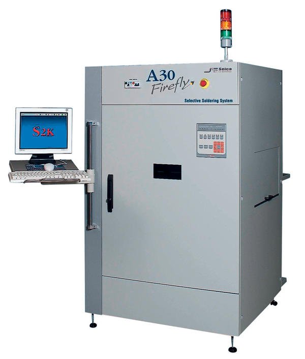
The availability of solid state laser devices has enabled the design of modern selective soldering systems that can cover the full range of technological requirements. Laser-based soldering is being implemented due to the capability it offers through the exploitation of a high energy beam that can be focused exclusively on the solder joint, without involving the board substrate and the surrounding components (even with the high temperatures required for lead-free alloys). With its Firefly Seica has developed a complete, high-performance laser-based selective soldering system. The many possible applications of the Firefly system include soldering of all through-hole as well as odd form components. Based on the information received from CAD and Gerber files, (or manually entered by the operator), dedicated algorithms automatically determines, for each solder joint the thermal profile, laser spot size and volume of solder required (calculated in terms of wire length). The soldering profile is made up of three phases:
- In the first phase a quantity of power is applied to warm up the component lead and the pad, and the wire is brought near the joint area.
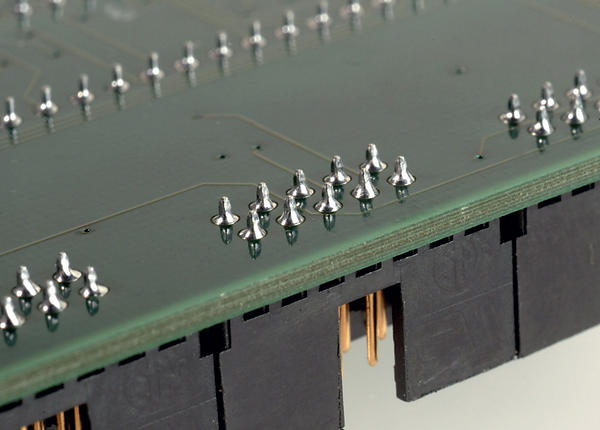
- During the second phase higher power is applied along with the wire; at this point the wire melts, the flux wets the soldering surfaces to perform its deoxidation and the melted alloy wets the pad and flows up into the hole to form the meniscus through to the top side of the board.
- In the third phase power is reduced to the temperature required to maintain the alloy melted in order to complete the joint wettability.
Since every single joint has its specific thermal mass, it also has a specific thermal profile. As on other thermal process machines, the soldering profile is characterized by the temperature trend of temperature over time, and is obtained by changing the powers and relative time during the three phases. Each joint has a specific thermal mass which is determined by the number and shapes of the traces merging on the point. In the case of multilayer boards there are connections to ground and power layers, and the heat dissipation characteristics of the components to be soldered changes case by case. The head is the core of the soldering system, since it contains the laser lens, the wire dispenser, the camera, the pyrometer and the planarity sensor. As an option a hot air blow element can be mounted in the work area to preheat the board to be soldered. The 60-watt laser unit, is located at the back of the system and the laser is routed through the optical fiber and focused by the motorized axes to the size programmed as required for each specific pad.
The wire dispenser can hold a 500 gr reel of various diameter wires ( 0,5 mm, 0,7 mm and 1 mm), and the wire feed is controlled via closed loop feedback from appropriately positioned sensors. The whole head can rotate more than 180 °; this feature allows the soldering angle to be changed and rotation during the soldering process, in order to achieve complete wettability in the case of large pads. The Z axis movement capability allows the soldering plane height to be varied (for each joint), to enable the soldering of components which may be assembled at different levels on the board.
Process measurement for complete control
Accurate, repetitive thermal transfer is among the several advantages of laser-based soldering compared to other technologies. Since it is a non-contact soldering technique, other advantages include the capability of forming the solder joint without stressing the board and components, without wearing out the bits (unlike hot iron robots) or producing waste (zero contamination). Since the laser spot dimension is variable and programmable, it is possible to work on different size pads without having to change soldering nozzles, as is necessary on mini-wave soldering machines. In addition to a high level of flexibility and process selectivity, laser-based soldering provides consistent quality throughout the production run, has been proven to be the most suitable technology on the market for Pb-free alloys without having to use inert gases. Obviously it is also possible to work with lead-based alloys, simply changing the solder alloy and the corresponding reference thermal profile.
Trying to provide a productivity average, 1,2 sec/joint might be suggested, but according to what has been said above, it would not be correct to define it as a target value (practice confirms both lower and higher levels) because there are several elements that come to influence it, all linked to specific characteristics of the single products. We can confirm for sure the absence of mechanic and thermal stresses, (only small parts of the board stand the thermal cycle), together with the absence of handling stresses (absence of frames and grips) or stresses caused by ESD problems.
EPP Europe 419
zusammenfassung
Vorgestellt wird ein selektives Lötsystem. Das hohe Laserenergieniveau und die präzise Aufbringung des Lötmaterials bei exakter Temperaturkontrolle gewährleisten ein effizientes Löten für jeden Baugruppentyp bei Verwendung sowohl bleifreier als auch bleihaltiger (SnPb) Legierungen. Das Löten durchkontaktierter Bauteile bedarf keiner Schutzmasken. Die Laser-Löttechnik garantiert hohe Lötstellenqualität bei minimaler Temperaturbelastung.
L’article présente un système de brasage sélectif. Le niveau élevé d’énergie laser et l’application exacte du produit de brasage avec un contrôle précis de la température assurent un brasage efficace pour chaque type de composant en cas d’utilisation d’alliages avec (SnPb) ou sans plomb. Le brasage de composants transversaux ne nécessite aucun masque de protection. La technique de brasage au laser garantit une haute qualité des points de brasage et une contrainte thermique minimale.
Viene presentato un sistema di saldatura selettivo. L’elevato livello di energia laser e la precisa introduzione del materiale di saldatura con controllo esatto della temperatura garantiscono una saldatura efficiente per ciascun tipo di componente, sia che si impieghino leghe senza piombo che leghe al piombo (SnPb). La saldatura di componenti con contatti passanti non richiede maschere protettive. La tecnica di saldatura al laser garantisce una elevata qualità dei punti saldati con sollecitazione termica minimale.
The flux cycle
The flux can be divided into two categories: resin based and water-soluble. The flux itself is not water-soluble; it is the residual waste after the soldering process that is water-soluble. It is important to remove the residual contamination after the soldering process. Ionic residuals left on the board may cause short circuits through the formation of dendrites, or corrosion, due to the electro migration. No-Clean (NC) residuals are hard, non-corrosive and inert. They can be left on the board or removed with an appropriate solvent.
Note: SIR = Surface Insulation Resistance / surface insulation test. Both terms resin and rosin are used. They are similar, but rosin indicates the natural resin; resin indicates the synthetic.
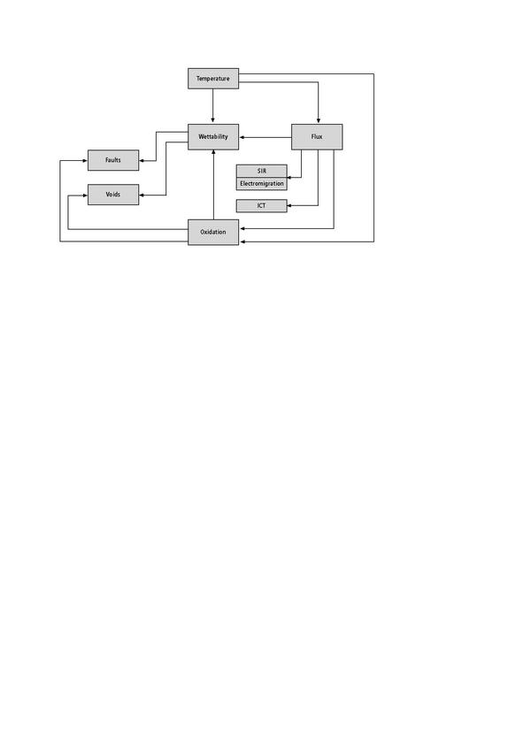
Soldering process interactions
Flow chart description: The purpose of using flux is to remove oxidation from the surfaces to be soldered to facilitate their wettability by the melted alloy. The flux must be able to de-oxidate pads and terminals at soldering temperature without decomposing. During the soldering process, the interaction between the metallic and chemical components affects the resulting solder joint. Temperature is the independent variable, central to the process, and has the highest impact on wettability. The flux contains organic substances that must survive at high temperatures, which become even higher in the case of a lead free alloy process. The flux is composed of activators, resin and solvents. When considering the influence of temperature on flux, we must focus our attention on three parameters:
- Evaporation of the solvent and of the volatile substances contained in the flux;
- Speed of distribution and viscosity of the solid substances under transformation;
- Decomposition of the original organic material contained in the flux;
The chemical and physical behavior of the flux directly affects:
- Surface insulation (SIR tests), electrical migration, waste formation
- In-circuit test results
Share:


