By mid-2006, toxic substances such as lead (Pb, plumbum) will have definitely been outphased in European electronic products. But before that, Japanese electronics manufacturers will have responded to this worldwide trend, and Chinese voices say they will follow the EU directive on RoHS (Reduction of Hazardous Substances). In a series of articles we will cover the transition and all its difficulties.
In previous articles (EPP EUROPE 1/2, 3/4, 5/6) we dealt with the establishment of soldering processes. Thus, we should have all the relevant basic information about the equipment. But when is a machine really lead-free compliant, and what does this mean? If users have not been very clear on many of the points when buying the equipment, they may have received a unit that the vendor considers lead-free capable which however may not perform to satisfaction within the lead-free process. Effects on equipment must be distinguished according to the type of solder: either alloys with substantially lower melting point, or formulations with substantially higher melting point. Those alloys with lower melting point (usually solder with bismuth, as indium would be too expensive) also exhibit a much lower presence of tin (around 50%). Typically, the tin content can be compared to that of eutectic SnPb-solders [1].
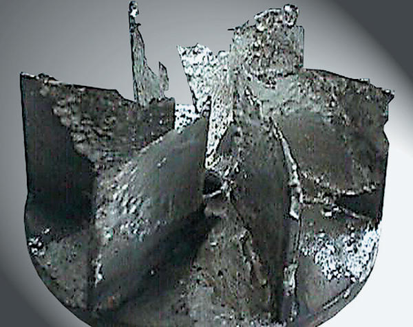
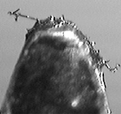
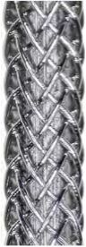
All those alloys that melt at higher temperatures approach pure tin. Their tin content lies above 90%, and in cases such as SnCu, the 0.6%-copper could be interpreted as ‘impurity’. It is important to understand that it is the tin which is the ‘aggressor’ that causes chemical reactions during soldering. The mechanism can be described as the creation of an intermetallic and then the dissolution. This leaching effect causes two problems: corroding machine pieces – especially moving parts, or where the solder has a high flow rate as friction adds to the chemical action (figure 1), and it contaminates the solder (figure 2). When examining equipment we have to keep in mind the alloy we want to use, and the possible detrimental effects of tin at higher temperature and percentage. However, lead-free-capable does not limit itself to material properties. It is important to make sure that the equipment can meet all the other process requirements that are needed for Pb-free solders.
The wave-soldering machine
Flow-soldering equipment consists in essence of the following parts: conveyor, fluxer, pre-heaters, soldering module and control unit. If we use a low-melting alloy with normal tin content, there is little we will have to demand. Because of the decreased wetting ability of the replacement solders, we would like to see nitrogen capability in our equipment. The absence of oxygen improves the wetting performance, and reduces the amount of dross and hence costs. A look at dross-data for different alloys and the cost of these compositions is quite enlightening. Depending on the amount of bismuth in the alloy, the metal can actually expand when solidifying. There is a real danger of cracking the pot if no pre-cautions are exercised. These may entail either ensuring that the solder will never freeze (power outage), or by using a solder pot that compensates for the expansion. Early experiments have indicated that the flux should be changed to something more suitable when using bismuth solders. Make sure that the fluxer allows for low maintenance, and for control of the amount of flux applied. With a move to an alloy with higher tin content and higher melting point, the entire situation becomes far more critical.
Conveyor – Smooth operation, parallel rails and chains/fingers to hold boards securely are most important. Furthermore, the designer of such a system for lead-free solders must understand the implications of a higher melting point (even higher temperatures already in the pre-heating section), and a lower density of the solder. He must take care that there is no chance of rail bending or warpage and that greases used on the conveyor are compatible with such temperatures. As the expansion of the PCBs will be increased (recommendation of components manufacturers to limit the temperature jump from preheat into the liquid solder to <100K), the ‘springiness’ of the fingers or the solder pallet have to account for it.
The lower density will affect the peel-back of the solder at the exit from the wave. If the same approximate conditions as for lead-bearing solders are to be achieved, measures have to be introduced to compensate for the lower weight. This can either be a steeper inclination of the conveyor or some other means such as different nozzle design. A vector diagram quickly shows that a steeper conveyor angle improves the rolling effect of the solder peel-back in direction of travel. If we thus manipulate the gravitational pull, we may calculate that angles between 7° to 9° may be required, and there are other properties such as viscosity, surface tension and the flux.
The disadvantage of increasing the conveyor angle is the height difference between entrance and exit. The handling with other units (integration of an oven into a line) might therefore become a problem. To improve the flow properties of lead-free alloys without the negative influences caused by the change of the conveyor angle, Seho slopes the solder nozzle up to 2°. This causes a steeper angle resulting in a higher flow speed of the alloy which neutralizes the worsened wetting properties of the solder. Compared to the angle adjustment, the change of the nozzle angle has a decisive advantage: the wetting length and time are kept on the same level without any readjustment of the solder pot height. Additionally, new nozzle designs can help to keep the conveyor angle at the traditional slope. Nozzle geometries which show higher flow properties are already used in various machines. As there is the possibility of ‘modified fluxes’, it should be ensured that the machine could keep these fluxes out of the conveyor system.
Fluxer – Search in the arsenal of chemical ‘weaponry’ has not brought the discovery of any more suitable activators than those used at present. There are of course better chemicals; however, they are either far too expensive, too rare, hard to come by, too toxic or have other undesirable properties. Hence, we seem to be stuck with the di-carbon series of acids. With their point of disassociation of about 160ºC, they are not suited to meet the requirements of higher temperatures. But it is not only the melting point of the solder that makes their application problematic, but also the stringent requirements of component manufacturers. During wave soldering it is likely that the preheat temperature will have to be increased to a level that fluxes have difficulty in coping with. Fail-ure of fluxes would be pre-programmed if no counter measures were taken. The most common proposal is an increase of the rosin content and a decrease of solvent. Switching the sequence of fluxing and pre-heating as we find it already in some selective-soldering machines in Japan may be another approach. It seems that the move to lead-free will also involve a re-awakening of cleaning operations.
Changes in flux make-up entail the fluid having to cope with higher viscosity and contamination. Proper exhaust and even a removal from the inside to the outside of the machine will keep maintenance at a minimum. A separate fluxing module in front of the soldering machine offers various advantages: ensuring minimum contamination of the process area, and offering more room to enlarge the preheat area for instance which is a must in case the conveyor speed is not reduced.
Preheaters – The function of the preheaters has two major aspects: temperature increase (grad-ient) of the assembly and achieving of a targeted temperature before entering the liquid solder. Thermally complex assemblies are heated with a gradient of between 0.5 and 2.0K/sec. Making a few assumptions, we will run through a calculation: solder temperature 285°C, temperature jump from preheat into liquid solder <100K, and conveyor speed 90cm/min. When using SnPb, the solder temperature was 250ºC, and preheat was 110ºC – measured on top of the laminate. For the lead-free process we thus would have to achieve a preheat of about 145ºC on the assembly – with maybe 160 to 170ºC on the bottom of the assembly (room temperature 20ºC).
Under these assumptions the temperature increase amounts to 120K. If we use a gradient of 2.0K/sec we have to dwell in the pre heat for 70 sec, and for a gradient of 0.5 K/sec, this augments to 280 sec – not including a plateau if necessary to evaporate solvents or water. The conveyor speed of 90cm/min translates then into a length of required preheat zone of 105cm, although for a gradient of 0.5K/sec the total length would be 4.2m. Not many ovens would meet that requirement. As an alternative, we could reduce the speed at least in the preheating area (split conveyor), so that we do not negatively affect the contact zone in the solder. Reducing the speed may be possible in many applications, however, and if no slack time is available during production it would translate into reduced throughput. So, users should check whether the configuration of the preheat area can be changed, e.g. by installing more powerful modules (quartz or convection instead of IR). By placing the fluxing module in a separate unit, the preheat zone can be enlarged.
Solder module – The most critical part in a wave-soldering machine is the pot where the liquid solder is contained and pumped. This is particularly true when we consider lead-free soldering with SnAg, SnAgCu or SnCu alloys. The normally used 305 or 316-steel alloys are not resistant enough to cope with tin aggressiveness at elevated temperatures. This has been known for some time, and as explained, parts that are subject to movement and possibly friction suffer the most. But certain areas of the walls also are attacked. There are some metals that seem to be resistant to leaching by tin (Hastelloy), but such material – it is proprietary – is expensive and extremely difficult to weld and cut. Thus the suppliers of wave-soldering equipment concentrated on pot coatings. What we see in different pieces of equipment shows the entire range of experiments – some more successful than others. It seems that many of them have only been tested under laboratory conditions as they may stand up to the task if they are left undisturbed. However, in real life, the pots and pumps are mistreated: scratching with screwdrivers during maintenance, or knocking pumps against concrete floors to dislodge stubborn dross particles, are common practice. Few coatings would endure the two-pronged attack of inconsiderate treatment and leaching. Even the best coating will be ‘under-eaten’ if it is cracked or chipped.
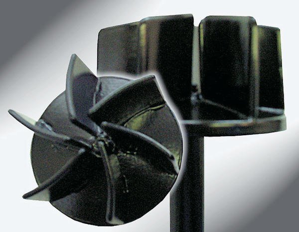
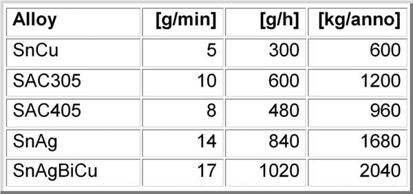
The pot treatments range from painting with Tef-lon (not recommended) via impregnating with titanium-nitrate to ceramic coatings. An in-depth discussion with the manufacturer is highly recommended. Figure 3 shows a composite coating which was jointly developed by Seho, industry partners and research institutes. This protective coating has been successfully used for years and is suited for all known lead-free alloys. The increased cost of dross will justify the use of an inert atmosphere by itself. Working without dross-reduction measures would be too expensive (table I). The improved wetting performance under nitrogen would then come as a fringe benefit. Without nitrogen, the process would need even higher process temperatures, something the materials would not easily forgive. A word about pot size: the larger the pot, the easier it is to generate a flow with little turbulence and greater depth. It also will take longer to exceed dangerous contamination levels. However, filling a large pot will be much more expensive as lead-free solders can cost ‘a pretty penny’.
Cooling – Check the options to cool the assemblies directly after soldering, before they leave the machine. An effective and fast cooling results in a very positive influence on the metallurgical structure of solder joints. Metallographic sections through joints which were processed without controlled cooling for instance show a distinct intermetallic phase (Cu6Sn5). The solder structure does not reveal homogeneous solidification.
Control unit – We would expect that at least the control unit would be free of additional demands. In applications where SnCu is in use for some time, it was frequently found that leaching of copper from boards and components caused a ‘run-away’ of the copper contents [4]. The phase diagram of SnCu shows that this is an unwelcome event. The liquidus curves do not rise as gently from the eutectic point as we are accustomed from SnPb or SnBi. In order to avoid problems, a real-time analyzer of the copper content would make a positive contribution to process control. The problem is also noted in SnAgCu (the popular alloy) to such an extent that users work only with SnAg and count on the leaching to make up the necessary copper content. Frequent testing recommended.
Reflow-soldering systems
We distinguish three main technologies: infrared radiation, convection and condensation heat transfer.
Infrared systems – There are few movable parts in such ovens. However, attention must be paid to the conveyor and maybe improved insulation. The basic problem why the infrared technology was moved off the market was its inability to provide small DT on the assembly. Potentially, this inadequacy could become more pronounced, as the temperature will have to be increased. Many such systems are relatively short and have problems already in SnPb-processes to maintain specific profiles over longer periods. It is unlikely that the situation would improve for alternative alloys. We have to question whether the DT will play the same important role in lead-free soldering as it has in traditional joining. If not, the argument reduces itself to the large temperature difference between the heater source and the target. Infrared equipment also will need the feature of inert atmosphere. It is never the soldering method proper that reduces wetting, but rather material contribution. Since the pastes will be based on somewhat higher rosin content, managing the tunnel atmosphere to minimize soiling of the interior is highly desirable.
Convection systems – Although reflow is “only” a managed heat transfer, there is still equipment that does not meet lead-free requirements. When thumbing through the maintenance record of a customer who is still running SnPb processes, we noticed that the ventilation unit in the peak zone had to be replaced every three months. This had become a preventive maintenance procedure. Motors and bearings were not able to cope with the peak temperature for longer periods. If machines have problems during SnPb-processing, we can assume that at 20 to 40K higher peaks the system is close to constant shut down. Again, the moving parts pose the problem. And even if the supplier provides replacement parts free of charge during an extended warranty period, the situation is not solved. It is not the cost of the repair, rather the downtime of the line that costs money. Large companies calculate the downtime of a major mass-production line to be around ê10,000 to 15,000. As a contact in such a company once put it: “After 10 hours of downtime the company can not only buy a better machine, but I can also find myself another job”.
Special attention therefore should be paid to high-quality blower units and motors which ideally are side-mounted, since top-located parts would be located in the hottest area. Increased process temperatures require a capable energy transfer. Heating zones which are not only located in the upper machine part but also in the bottom area, combined with optimized gas circulation (tangential fans), ensure an effective and component-sensitive heating. Therefore, setting of low oven temperatures is possible, and with lead-free soldering, it is important since the stress on components will be reduced. At the same time, the oxidation rate will be kept as low as possible. Systems with multi-peaks (double or triple) ensure a very flexible temperature profiling.
Nitrogen capability is another requirement. The worsened wetting situation must be compensated by nitrogen and not by even higher temperatures. Low consumption and a reasonable level of residual oxygen (ROL) are the targets. Consumption can be lowered, and resources and money can be saved if reasonable ROL values (100ppm in the peak zone) satisfy the requirements. As pointed out, we expect higher rosin content in pastes, and hence insist on better flux traps and gas-management. Stalagmites and stalactites look pretty in caves but not in convection tunnels. Not only do they ask for maintenance but they also pose danger to the assemblies. The oven should be equipped with a multi-stage condensate management (infeed, heating zone, cooling zone and exit). A filterless flux management provides some advantages since filters may gradually clog and thus influence the process negatively.
The higher temperatures will be close – if not above – the glass transition area of the laminate. We expect more problems with warpage and deformation of the PCB – and that is what is seen already. Once the PCB has lost some of its stiffness, it has to be supported. An adjustable center support can often help, if the layouter has accounted for such features. At the exit, cooling defines the crystalline structure of the joints. We still lack information on desirable cooling rates. But we do know that the replacement alloys can create different crystalline structures, depending on the cooling rate. Research tries to identify the ‘best’ crystalline structure and the cooling rate to achieve it. As the results will be available soon, we require adjustable cooling at machine exit.
Condensation-soldering
In condensation systems, the reflow temperature is most often (at least in saturated vapor) defined by the boiling point of the liquid. For alloys with higher melting points, the liquid has to be changed to match boiling with melting point. Research carried out at the Technische Universität Dresden (Prof. Wolters) indicates that a lower super heat (melting point of alloy to boiling point of liquid = process temperature) may be used in reflow processes. The reason may be seen in the very low level of residual oxygen present in the vapor. As there are many different liquids available with a large range of boiling points, we do not see any problems arising from requirements posed on chemicals. The thermal profiling of condensation reflow is largely controlled by the conveyor speed. Changing the heating capacity is only used for some preheating technology. The question whether such systems are lead-free compatible seems to limit itself to an assessment of the heating capability and the energy requirements of the higher boiling-point liquids can be met.
Although a liquid has only a limited ability to dissolve rosin, it would accumulate in the sump if it were not filtered out. For the new pastes, better or more frequent filtering may become an issue. This is a maintenance-related issue as the vapor, being a distilled phase, is clean even if the sump has been contaminated. Modern equipment is well insulated and though the temperature inside will be increased by 10 to 20K, the surface should remain within acceptable limits. In most machines the conveyor is basket-like and does not require any additional support, except perhaps for double-sided reflow. What has been said for the crystalline structure when discussing convection-reflow equipment also holds for condensation reflow. Cooling rates at the exit have to be ‘settable’, otherwise we may be left without the means to produce optimal solder joints.
Other soldering processes
From the main-soldering processes we may collect those aspects that also apply to other procedures. During selective soldering, either liquid solder (mini-waves) or reflow methods (hot gas or laser) are applied. However, all aspects are less problematic as the processes are only selective and do not affect the entire assembly. Especially in case of mini-wave soldering, lead-free processes do not differ much compared to the SnPb-soldering, providing that ideal peel-off angles can be achieved with flexible handling (gripper) systems (tilting, turning of assemblies). The changing flow pattern of lead-free alloys is not relevant. From the material side, protective measures (for pots, pumps, etc.) have to be considered with regard to the aggressiveness of lead-free alloys.
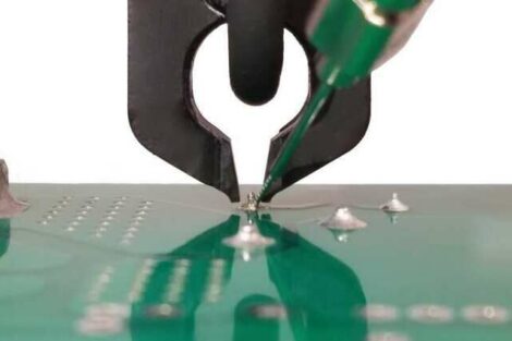
The situation is different for hand soldering. The life of the iron tips will be reduced substantially. And, if several alloys will be in use, the control of the proper tip temperature (melting point of the alloy +70K for the heat-sinking experienced during soldering + approx. 35 to 50K super heat to ensure proper flow and wetting) will be more difficult than in recent times. The difference in melting point would ideally translate into different tip temperatures for each alloy. Maybe the solder-station suppliers could provide color-coding of the different pre-selected settings?
During the assessment of the equipment, a user could come up with a wish list that he could compare to the present situation. These are questions such as: which equipment features do we really need? Do we have the right equipment and tools? Can we upgrade or do we need to purchase new systems? Do we have cost estimates? Which vendor offers the optimal equipment, service and advice for us?
EPP EUROPE 405
References
[1] Schroeder, V. et al.: Applicability of Bi-42Sn-1Ag Solder for Consumer Products. Apex 2002
[2] A. Rahn & T. Raisch: Lead-free Soldering of BGA Packages. IEEE Symposium on High Density Packaging and Component Failure Analysis in Electronics Manufacturing, Shanghai 2002
[3] C. C. Dong et al.: Effects of Atmosphere Composition on Soldering Performance of Lead-Free Alternatives. Nepcon West, Anaheim 1997
[4] A. Grusd: Integrity of Solder Joints from Lead-free Solder Paste. Nepcon West, Anaheim 1999
Industry has to set own target dates
We read in the Directive of the European Parliament and of the Council on the Restriction of the Use of Certain Hazardous Substances in Electrical and Electronic Equipment, given at Brussels, No-vember 8, 2002, under 2000/0159 (COD) – C5–0487/2002 – PE-CONS 3662/02 – ENV 581 – CODEC 1273 the following:
Article 4, Prevention 1. Member States shall ensure that, from 1st July 2006, new electrical and electronic equipment put on the market does not contain lead, mercury, cadmium, hexavalent chromium, polybrominated biphenyls (PBB) or polybrominated diphenyl ethers (PBDE).
We felt that the term ‘put on the market’ needs some clarification as manufacturers of electronic equipment may not be clear about it and the implications it has for the target date. We enquired about it at the Ministry of the Environment in Berlin/Germany and received the answer that ‘put on the market’ means delivery of the product to the enduser. This clarification makes it obvious that the industry has to set its own target dates depending on the time it takes them to bring products from manufacturing to the enduser. Furthermore, it will be important to clear all intermediate products containing lead out of the ‘delivery pipeline’ before this date, or to ensure that such a product is only delivered to customers outside of the EU where the directive does not apply, and to cus-tomers who have not specified lead-free products. By the way, manufacturers may continue to use lead in products that will not be put on the market in the EU even after 2006. Whether this exception will make things easier for the industry has to be judged by the individual manufacturer.
Share:


